Written by Abhijit Bose, an Embedded, Analog and Hardware Engineer and new member of the Zephyr community
This blog originally ran on Abhijit’s personal website. For more content like this, click here.
After understanding the basics of how to do debugging on a Zephyr RTOS project, let’s do something custom.
We would look at how to get started with Application Development on Zephyr OS.
This is Part 3 in the series of post on Zephyr OS. In Part 1 we saw how to setup the development environment on Manjaro (Arch Linux). In Part 2 we looked at how to create an Eclipse CDT IDE end project and then successfully debug our code.
Source code for
basic-blinkyproject is available at https://github.com/boseji/zephyr-basic-blinky-stm32f3_disco .
Source code for
fancier-blinkyproject is available at https://github.com/boseji/zephyr-fancier-blinky-stm32f3_disco . Note: This code is specific for STM32F3 Discovery with PCB Revision C and above.
As you might have guessed by the image on this post.
Yes we are going to use our favorite STM32F3 Discovery board.
Last time we had a more casual look at this wonderful STM32F3 Discovery board. This time we are going to have a closer look at the board.
In this journey towards Application Development in Zephyr OS – We would like to start by making a program to blink a specific LED on STM32F3 Discovery board. And later we would make a pattern by blinking all the LEDs on this board.
1. Closer look at STM32F3 Discovery #
Let’s start by obtaining the schematics for this board.
Resources -> Hardware Resources -> SCHEMATICS – Website navigation
Here is the direct link:https://www.st.com/resource/en/schematic_pack/stm32f3discovery_sch.zip
Note: You might need to sign-up on ST Micro website to get this document.
After extract it you would get a PDF file – MB1035.pdf
( Download File – Right-Click and SaveAs).
That is the PDF Converted output of the schematics in Altium Designer.
1.a On-Board LEDs #
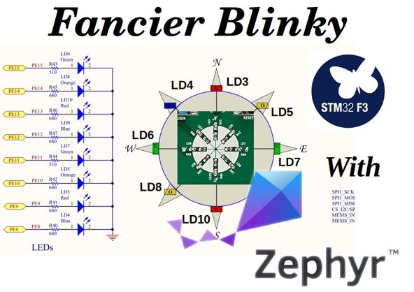
STM32F3 Discovery has 8 User LED and 2 LEDs on the debugger side (ST-LINK/V2-1).
| S.No | LED | GPIO PORT | GPIO PIN | Color | DTS Label | DTS Alias |
|---|---|---|---|---|---|---|
| 1 | LD3 | PORTE | 9 | Red | red_led_3 | – |
| 2 | LD5 | PORTE | 10 | Orange | orange_led_5 | – |
| 3 | LD7 | PORTE | 11 | Green | green_led_7 | led1 |
| 4 | LD9 | PORTE | 12 | Blue | blue_led_9 | – |
| 5 | LD10 | PORTE | 13 | Red | red_led_10 | – |
| 6 | LD8 | PORTE | 14 | Orange | orange_led_8 | – |
| 7 | LD6 | PORTE | 15 | Green | green_led_6 | led0 |
| 8 | LD4 | PORTE | 8 | Blue | blue_led_4 | – |
(Listing in clockwise order)
Here is snap from the Schematics showing the 8 User LEDs of STM32F3 Discovery board:

All LEDs are in Active-High type Drive configuration.
You might wonder what is DTS Label and DTS Alias. Well these two come from the Device Tree Definition File or .dts file of STM32F3 Discovery board. In short it tells Zephyr OS what drivers are available for STM32F3 Discovery board and how they need operate. This is a slightly advance topic. May be material for a future post.
We would begin by blinking the LD3 or PE9. Then we would develop into a better version by including all the LEDs.
1.b On-Board Buttons #
There are 2 Tact-Key Buttons in STM32F3 Discovery.
The Blue one is a User Button.
The Black button (B2) is for Reset.

| S.No | Button | GPIO PORT | GPIO PIN | Color | DTS Label | DTS Alias |
|---|---|---|---|---|---|---|
| 1 | B1 | PORTA | 0 | Blue | user_button | sw0 |
1.c On-Board L3GD20H 3-axis Gyroscope #
STM32F3 Discovery has an interesting 3-axis Gyroscope.
L3GD20H is a 3-axis SPI Gyroscope with best in class angular rate detection.
One can easily detect tilt, swing and wobble movements of the STM32F3 Discovery board.
Its connected via the SPI1 Port.

This would be another future Article.
1.d On-Board LSM303DLHC – 3D Linear Acclerometer , 3D Magnetic sensor #
The LSM303DLHC is a system-in-package featuring a 3D digital linear acceleration sensor and a 3D digital magnetic sensor.
The LSM303DLHC has linear acceleration full scales of ±2g / ±4g / ±8g / ±16g and a magnetic field full scale of ±1.3 / ±1.9 / ±2.5 / ±4.0 / ±4.7 / ±5.6 / ±8.1 gauss.
The LSM303DLHC includes an I2C serial bus interface that supports standard and fast mode 100 kHz and 400 kHz. The system can be configured to generate interrupt signals by inertial wake-up/free-fall events as well as by the position of the device itself. Thresholds and timing of interrupt generators are programmable by the end user. Magnetic and accelerometer blocks can be enabled or put into power-down mode separately.
Source : ST Micro Website
This is connected via I2C Bus. Though the chip is little old (currently OBSOLETE), it can be useful for another Article.

Let’s now look at the Zephyr OS API that we need to use.
2. Zephyr OS : API Reference #
To use the full features of Zephyr OS as it’s power we need to make ourselves aware of the API that we have at hand.
Let’s look at our last Blinky Example (src/main.c file):
7 8 9 10 11 | #include <zephyr.h> #include <device.h> #include <devicetree.h> #include <drivers/gpio.h> ... |
This quickly gives us the idea of the API that we need to access to create our similar program.
2.a Device Driver API #
This is represented by following in Blinky Example (src/main.c file):
#include <device.h>
This needed for the following function:
1 2 3 4 5 | dev = device_get_binding(LED0); if (dev == NULL) { return; } |
This function retrieves a handle device being request. In this case its LED0. The actual signature is as follows
struct device *device_get_binding(const char *name)
For more insight:https://docs.zephyrproject.org/latest/reference/drivers/index.html#_CPPv418device_get_bindingPKc
In our case we need to blink an LED on PORTE. However as per Device Driver Model of Zephyr OS we call it GPIOE.
Additionally you might have noticed the if (dev == NULL) part. This is basically to ensure that we only continue the execution of the program if we get the device handle. Else we stop execution.
Let’s look at how we would get our PORTE device handle.
1 2 3 4 5 6 7 | struct device *gpioe = (struct device *)NULL; gpioe = device_get_binding("GPIOE"); if (dev == NULL) { return; } |
2.b Device Tree API #
This is represented by following in Blinky Example (src/main.c file):
#include <devicetree.h>
This needed for the following Defines:
1 2 3 4 5 6 7 8 9 10 11 12 13 14 15 16 17 18 19 | /* The devicetree node identifier for the "led0" alias. */ #define LED0_NODE DT_ALIAS(led0) #if DT_NODE_HAS_STATUS(LED0_NODE, okay) #define LED0 DT_GPIO_LABEL(LED0_NODE, gpios) #define PIN DT_GPIO_PIN(LED0_NODE, gpios) #if DT_PHA_HAS_CELL(LED0_NODE, gpios, flags) #define FLAGS DT_GPIO_FLAGS(LED0_NODE, gpios) #endif #else /* A build error here means your board isn't set up to blink an LED. */ #error "Unsupported board: led0 devicetree alias is not defined" #define LED0 "" #define PIN 0 #endif #ifndef FLAGS #define FLAGS 0 #endif |
This might be very confusing. Why on earth we do this ?
Don’t worry you are in the right company. – @boseji
2.c Device Tree API : Explanation for DT_ALIAS Macro #
If you remember from our table of GPIO we had DTS Alias.
Well in the Device Tree a DTS Alias assigns a alternative label to the original device name.
Let’s look at one.
| S.No | LED | GPIO PORT | GPIO PIN | Color | DTS Label | DTS Alias |
|---|---|---|---|---|---|---|
| 7 | LD6 | PORTE | 15 | Green | green_led_6 | led0 |
This is how it looks inside the stm32f3_disco.dts file for STM32F3 Discovery board:https://github.com/zephyrproject-rtos/zephyr/blob/master/boards/arm/stm32f3_disco/stm32f3_disco.dts
...
    leds {
...
        green_led_6: led_6 {
            gpios = <&gpioe 15 GPIO_ACTIVE_HIGH>;
            label = "User LD6";
        };
...
    };
...
    aliases {
        led0 = &green_led_6;
        led1 = &green_led_7;
        sw0 = &user_button;
    };
...
You can clearly see the redirect of led0 = &green_led_6;. This is what we are doing in the first line.
15 16 | /* The devicetree node identifier for the "led0" alias. */ #define LED0_NODE DT_ALIAS(led0) |
The macro DT_ALIAS fetches the led0 from Device Tree of STM32F3 Discovery Board. Hence LED0_NODE becomes green_led_6 which is the device name.
Though all these were used in the Blinky example. We are not going to use these in our custom example.
For further insight:https://docs.zephyrproject.org/latest/reference/devicetree/index.html#c.DT_ALIAS
Explanation for DT_NODE_HAS_STATUS Macro #
The DT_NODE_HAS_STATUS Macro helps us to check if a particular node does exist in the Device Tree of the respective board.
Note: Pre-processor detects things in the Device Tree of the respective board in Zephyr OS in a different way. It would throw a compiler error.
Let’s look at how this works.
#if DT_NODE_HAS_STATUS(LED0_NODE, okay)
...
#else
/* A build error here means your board isn't set up to blink an LED. */
#error "Unsupported board: led0 devicetree alias is not defined"
#define LED0	""
#define PIN	0
#endif
...
The first line DT_NODE_HAS_STATUS(LED0_NODE, okay) is evaluated at compile time. The only way it becomes false only, if the board does not have the led0 alias defines. This would then raise the error "Unsupported board: led0 devicetree alias is not defined".
In case of STM32F3 Discovery Board the led0 alias is defined. Hence DT_NODE_HAS_STATUS(LED0_NODE, okay) would evaluate to true.
Note: The value
okayis a defined value equivalent to “ok” for status.
Though all these were used in the Blinky example. We are not going to use these in our custom example.
For more insight:https://docs.zephyrproject.org/latest/reference/devicetree/index.html#c.DT_NODE_HAS_STATUS
2.d Device Tree API : Explanation for DT_GPIO_LABEL Macro #
This Macro helps to obtain the GPIO or port number.
The following would fetch GPIOE as the value of LED0:
#define LED0 DT_GPIO_LABEL(LED0_NODE, gpios)
Since, STM32F3 Discovery board has the led0 an alias for green_led_6. Which intern is a specific GPIO PE15 defined by <&gpioe 15 GPIO_ACTIVE_HIGH>; in the .dts file we discussed earlier.
Though all these were used in the Blinky example. We are not going to use these in our custom example.
For more insight:https://docs.zephyrproject.org/latest/reference/devicetree/index.html#c.DT_GPIO_LABEL
2.e Device Tree API : Explanation for DT_GPIO_PIN Macro #
This helps to find out the pin number for the respective node name in case of GPIO.
#define PIN DT_GPIO_PIN(LED0_NODE, gpios)
This line for STM32F3 Discovery means it refers to led0 -> green_led_6. Hence it would GPIOE or PORTE pin 15.
The value of PIN from above becomes 15.
This would be useful for the Peripheral GPIO API we would discuss in the next section.
Though all these were used in the Blinky example. We are not going to use these in our custom example.
For more insight:https://docs.zephyrproject.org/latest/reference/devicetree/index.html#c.DT_GPIO_PIN
2.f Device Tree API : Explanation for DT_PHA_HAS_CELL & DT_GPIO_FLAGS Macro #
This macro checks if the particular node has an flags. Typically for big microcontroller there are many parameters that need to passed to configure the GPIO. These may be defined in the .dts of the respective board. Hence we need to provide the same during GPIO initialization. This macro tells us if we need to look at flags or not.
...
#if DT_PHA_HAS_CELL(LED0_NODE, gpios, flags)
#define FLAGS	DT_GPIO_FLAGS(LED0_NODE, gpios)
#endif
...
That’s why it inside the #if def.
The next macro DT_GPIO_FLAGS helps to pull out those flags to FLAGS symbol.
In our case STM32F3 Discovery does not have any flags for GPIO. Hence the DT_PHA_HAS_CELL(LED0_NODE, gpios, flags) becomes false.
That’s why we have the other block:
...
#ifndef FLAGS
#define FLAGS	0
#endif
...
Though all these were used in the Blinky example. We are not going to use these in our custom example.
For further insight:
- https://docs.zephyrproject.org/latest/reference/devicetree/index.html#c.DT_PHA_HAS_CELL
- https://docs.zephyrproject.org/latest/reference/devicetree/index.html#c.DT_GPIO_FLAGS
2.g Peripheral GPIO API #
In order to interact with the GPIO we need to use the Peripheral driver.https://docs.zephyrproject.org/latest/reference/peripherals/gpio.html
For us there are 2 important functions:
    ...
    ret = gpio_pin_configure(dev, PIN, GPIO_OUTPUT_ACTIVE | FLAGS);
    if (ret < 0) {
        return;
    }
    ...
        gpio_pin_set(dev, PIN, (int)led_is_on);
    ...
Here are the signatures:
static int gpio_pin_configure(struct device *port, gpio_pin_t pin, gpio_flags_t flags)

static int gpio_pin_set(struct device *port, gpio_pin_t pin, int value)
However I would prefer to use the toggle API since it saves us one more variable:
static int gpio_pin_toggle(struct device *port, gpio_pin_t pin)
For our PE9 on STM32F3 Discovery board it would become:
    ...
    ret = gpio_pin_configure(gpioe, 9, GPIO_OUTPUT_ACTIVE);
    ...
        gpio_pin_toggle(gpioe, 9);
    ...
For further insight:
- https://docs.zephyrproject.org/latest/reference/peripherals/gpio.html
- https://docs.zephyrproject.org/latest/reference/peripherals/gpio.html#c.GPIO_OUTPUT_ACTIVE
- https://docs.zephyrproject.org/latest/reference/peripherals/gpio.html#_CPPv418gpio_pin_configureP6device10gpio_pin_t12gpio_flags_t
- https://docs.zephyrproject.org/latest/reference/peripherals/gpio.html#_CPPv412gpio_pin_setP6device10gpio_pin_ti
2.h Zephyr OS Kernel Services : Threads API #
In order to perform timing delays, we need help from Zephyr OS. Hence the Kernel Services API.
This is need for our delay function :
        ...
        k_msleep(SLEEP_TIME_MS);
        ...
This is the Thread sleep function:
Here is the function signature:
static int32_t k_msleep(int32_t ms)
The parameter ms is in milliseconds units (1second = 1000 millisecond).
For further insight:
- https://docs.zephyrproject.org/latest/reference/kernel/threads/index.html
- https://docs.zephyrproject.org/latest/reference/kernel/threads/index.html#_CPPv48k_msleep7int32_t
3. Zephyr OS Application Development : Creating basic-blinky #
Now that we have looked into the Zephyr OS API, we have fair idea of how our main program would look like.
Let’s re-iterate our goals:
- Enable
PE9or LD3 Red LED as an Output - Toggle the
PE9every 1 Second
These goals would help us shape the basic-blinky program.
3.a Creating the Directory Structure for project basic-blinky #
Continuing from last time , where we had already setup the Workspace directory.
Let’s now look at creating our directory structure for the basic-blinky project :
1 2 3 4 5 6 7 8 | # Go the Workspace cd ${HOME}/Workspace # Run the Environment Configuration script source ${HOME}/Workspace/env.sh # Create Our Source directory mkdir -p ${HOME}/Workspace/03_basic-blinky-stm32f3_disco/src |
We are creating the directory as
03_basic-blinky-stm32f3_disco. This time we are creating some thing specific to a particular board only.
3.b Project Configuration Kconfig #
The project configuration is held by Kconfig.
The Zephyr kernel and subsystems can be configured at build time to adapt them for specific application and platform needs. Configuration is handled through Kconfig, which is the same configuration system used by the Linux kernel. The goal is to support configuration without having to change any source code.
Source : Zephyr Documentation
For further reading:https://docs.zephyrproject.org/latest/guides/kconfig/index.html
Let’s create that:
1 2 3 4 5 6 7 8 9 10 11 12 13 14 15 16 | # Go the Workspace cd ${HOME}/Workspace # Run the Environment Configuration script source ${HOME}/Workspace/env.sh # Go to project directory cd ${HOME}/Workspace/03_basic-blinky-stm32f3_disco # Create our 'Kconfig' project Configuration # First we beed to use GPIO echo "CONFIG_GPIO=y" > prj.conf # Next we also need Debug Capability echo "CONFIG_DEBUG=y" > prj.conf |
3.c Build Configuration using cmake #
We already know about cmake and how it helps us generate project build.
Let us look at the default CMakeLists.txt that comes with the standard blinky project:
1 2 3 4 5 | cmake_minimum_required(VERSION 3.13.1) find_package(Zephyr REQUIRED HINTS $ENV{ZEPHYR_BASE}) project(blinky) target_sources(app PRIVATE src/main.c) |
Now, let’s try to understand each line:
- The first line tells
cmakethat we need at least version3.13.1ofcmake toolto run. - Next we ask
cmaketo locate Zephyr directory using an environment variableZEPHYR_BASE. - This defines the name of our project
blinky. Note: This does not relate to the directory we are storing our project. - Which sources to compile for our application.
Let’s add the same file to our project basic-blinky:
1 2 3 4 5 6 7 8 9 10 11 12 13 14 15 16 | # Go the Workspace cd ${HOME}/Workspace # Run the Environment Configuration script source ${HOME}/Workspace/env.sh # Go to project directory cd ${HOME}/Workspace/03_basic-blinky-stm32f3_disco # Create the CMakeList.txt Line by Line echo "cmake_minimum_required(VERSION 3.13.1)" > CMakeLists.txt echo "find_package(Zephyr REQUIRED HINTS $ENV{ZEPHYR_BASE})" >> CMakeLists.txt echo "project(basic_blinky_stm32f3_disco)" >> CMakeLists.txt echo >> CMakeLists.txt echo "target_sources(app PRIVATE src/main.c)" >> CMakeLists.txt |
You can also do the same in your favorite editor as well.
3.d The Main Program of Project basic-blinky #
Here how the src/main.c would look like:
${HOME}/Workspace/03_basic-blinky-stm32f3_disco/src/main.c
1 2 3 4 5 6 7 8 9 10 11 12 13 14 15 16 17 18 19 20 21 22 23 24 25 26 27 | #include <zephyr.h> #include <device.h> #include <devicetree.h> #include <drivers/gpio.h> void main(void) { struct device *gpioe; /* Get instance of GPIOE */ gpioe = device_get_binding("GPIOE"); if (gpioe == NULL) { return; } /* Enabled Pins for Output */ if (gpio_pin_configure(gpioe, 9, GPIO_OUTPUT_ACTIVE) < 0) { return; } /* Start the Infinite Loop */ while(1) { gpio_pin_toggle(gpioe, 9); /* Wait for 1 Second = 1000mS */ k_msleep(1000); } } |
We need to create this under ${HOME}/Workspace/03_basic-blinky-stm32f3_disco/src directory.
Note: that keeping this
main.cunder thesrcis a convention of Zephyr OS we are following.
3.e Building Project basic-blinky #
Now we have all the pieces in place for Project basic-blinky.
Let’s build it:
1 2 3 4 5 6 7 8 9 10 11 12 13 14 15 16 17 | # Go the Workspace cd ${HOME}/Workspace # Run the Environment Configuration script source ${HOME}/Workspace/env.sh # Create the Build Directory mkdir -p ${HOME}/Workspace/03_build_basic-blinky-stm32f3_disco # Change to the correct Build Directory cd ${HOME}/Workspace/03_build_basic-blinky-stm32f3_disco # Generate the 'Eclipse` enabled build configuration cmake -G "Eclipse CDT4 - Ninja" -DBOARD=stm32f3_disco ${HOME}/Workspace/03_basic-blinky-stm32f3_disco # We can even build it using 'west' tool west build |
We know that there is a caveat in flashing that we discussed earlier.
STM32F3 discovery Board with PCB version C and ST-LINK/V2-B we need to use:
1 2 3 4 5 6 7 8 | # Go the Build directory cd ${HOME}/Workspace/03_build_basic-blinky-stm32f3_disco # Direct flashing command using 'openocd' openocd -s /usr/share/openocd/scripts \ -f interface/stlink-v2-1.cfg \ -f target/stm32f3x.cfg \ -c "program zephyr/zephyr.bin verify reset exit 0x08000000" |
Other wise with the older STM32F3 discovery Board:
1 2 3 4 | # Go the Build directory cd ${HOME}/Workspace/03_build_basic-blinky-stm32f3_disco west flash |
We would later fix this issue in a different manner.
In case the programming fails. Just hold the Reset Black Tact-Key. And then execute the command. This should force the STM32 to go into CMSIS-Reset mode.
Success At Last… #
You should now see the Red LED LD3 blinking.
I have provided the full source code of basic-blinky project as a Github repository.
4. Creating the fancier-blinky Project #
Well we now have a working project where, we are able to blink an LED. There are 7 More LEDs. Let’s look at how we can extend our basic-blinky into fancier-blinky project.
Our goals for fancier-blinky project:
- Initialize all the 8 LED on STM32F3 Discovery board
- Display a rotating pattern using the LEDs
- Be able to flash the code using
westinstead of the largeopenocdcommand
4.a Prepare the project Directory for fancier-blinky #
First we clone our work in the basic-blinky:
1 2 3 4 5 6 7 8 | # Go the Workspace cd ${HOME}/Workspace # Copy the 'basic-blinky' Directory cp -rT 03_basic-blinky-stm32f3_disco 04_fancier-blinky-stm32f3_disco # Create the Build directory for 'fancier-blinky' mkdir ${HOME}/Workspace/04_build-fancier-blinky-stm32f3_disco |
4.b Alter the Main program for fancier-blinky #
We need to access all the 8 LEDs. Fortunately all the LEDs are on PORTE. We just need to store the pin number.
For that we would store them in an Array. It would be easy for initialization as well as rotating effect.
Lets look at the source code:
${HOME}/Workspace/04_fancier-blinky-stm32f3_disco/src/main.c
1 2 3 4 5 6 7 8 9 10 11 12 13 14 15 16 17 18 19 20 21 22 23 24 25 26 27 28 29 30 31 32 33 34 35 36 37 38 39 40 41 42 43 44 45 46 47 | #include <zephyr.h> #include <device.h> #include <devicetree.h> #include <drivers/gpio.h> void main(void) { struct device *gpioe; int i; /* LED Pins */ uint8_t pins[] = {9 /*LD3*/, 10 /*LD5*/, 11 /*LD7*/, 12 /*LD9*/, 13 /*LD10*/, 14 /*LD8*/, 15 /*LD6*/, 8 /*LD4*/}; /* Get instance of GPIOE */ gpioe = device_get_binding("GPIOE"); if (gpioe == NULL) { return; } /* Enabled All pins for Output*/ for (i=0;i<sizeof(pins);i++) { gpio_pin_configure(gpioe, pins[i], GPIO_OUTPUT_ACTIVE); } /* Perform Initial configuration */ i = 0; gpio_pin_set(gpioe, pins[i], 0); /* For the fist time OFF */ /* Start the Infinite Loop */ while (1) { /* First GPIO Toggle */ gpio_pin_toggle(gpioe, pins[i]); /* Increment the Counter avoiding overflow */ if (i < sizeof(pins)-1) { i++; } else { i = 0; } /* Second GPIO Toggle - give the ripple effect */ gpio_pin_toggle(gpioe, pins[i]); /* Wait for a short time */ k_msleep(1000); }/* End of While */ } |
The logic is very simple it’s intended to keep flipping alternate LEDs.
4.c Let’s Build and Observe the fancier-blinky in action #
Remember the distinction for the STM32F3 Discovery Board versions discussed earlier.
1 2 3 4 5 6 7 8 9 10 11 12 13 14 15 16 17 18 19 20 | # Run the Environment Configuration script source ${HOME}/Workspace/env.sh # Change to the correct Build Directory cd ${HOME}/Workspace/04_build-fancier-blinky-stm32f3_disco # Generate the 'Eclipse` enabled build configuration cmake -G "Eclipse CDT4 - Ninja" -DBOARD=stm32f3_disco \ ${HOME}/Workspace/04_fancier-blinky-stm32f3_disco # We can even build it using 'west' tool west build # Let's Flash the Code west flash # OR for PCB Version C openocd -s /usr/share/openocd/scripts \ -f interface/stlink-v2-1.cfg \ -f target/stm32f3x.cfg \ -c "program zephyr/zephyr.bin verify reset exit 0x08000000" |
You should now have a rotating ring on LEDs.
4.d Fixing the STM32F3 Discovery PCB revision C Flashing Issue #
These modification are only needed if you have a STM32F3 Discovery which is PCB revision C like me. These would not work for the older board versions.
As promised earlier, lets fix the issue for Flashing.
For normal STM32F3 Discovery older board its alright. But for my PCB revision C board using openocd directly is cumbersome and hard to remember.
We would use a facility of the Zephyr SDK to create Custom Boards.https://docs.zephyrproject.org/latest/application/index.html#custom-board-devicetree-and-soc-definitions
Custom Board, DeviceTree and SOC Definitions In cases where the board or platform you are developing for is not yet supported by Zephyr, you can add board, DeviceTree and SOC definitions to your application without having to add them to the Zephyr tree.
Let’s copy board definition files for STM32F3 Discovery to our project.
1 2 3 4 5 6 7 8 9 | # Change to the `fancier-blinky` project cd ${HOME}/Workspace/04_fancier-blinky-stm32f3_disco # Create the Board Directory as per 'Zephyr' Project guidelines mkdir -p boards/arm # Copy the 'STM32F3 Discovery' from 'Zephyr' cp -rT ${HOME}/Workspace/zephyr/boards/arm/stm32f3_disco \ boards/arm/stm32f3_disco |
Next we need to change the openocd.cfg file in boards/arm/stm32f3_disco/support directory. Just the first 2 lines.
We need to include the -f interface/stlink-v2-1.cfg -f target/stm32f3x.cfg from the openocd command.
Here is how the modification looks like:
Modified:
${HOME}/Workspace/04_fancier-blinky-stm32f3_disco/boards/arm/stm32f3_disco/support/openocd.cfg
source [find interface/stlink-v2-1.cfg]
source [find target/stm32f3x.cfg]

$_TARGETNAME configure -event gdb-attach {
	echo "Debugger attaching: halting execution"
	reset halt
	gdb_breakpoint_override hard
}

$_TARGETNAME configure -event gdb-detach {
	echo "Debugger detaching: resuming execution"
	resume
}
Next we need to modify our cmake configuration to enable our custom version of STM32F3 Discovery. For that we need to modify the CMakeLists.txt of our fancier-blinky project.
Modified:
${HOME}/Workspace/04_fancier-blinky-stm32f3_disco/CMakeLists.txt
1 2 3 4 5 6 7 8 | cmake_minimum_required(VERSION 3.13.1) set(BOARD_ROOT ${CMAKE_CURRENT_LIST_DIR}) set(BOARD stm32f3_disco) find_package(Zephyr REQUIRED HINTS $ENV{ZEPHYR_BASE}) project(basic_blinky_stm32f3_disco) target_sources(app PRIVATE src/main.c) |
The parameter BOARD_ROOT points where the board files exist. This time instead of zephyr/boards to our 04_fancier-blinky-stm32f3_disco/boards. Additionally we are also specifying the board name in BOARD parameter.
Note: With the above modification in
CMakeLists.txtit would no longer work for older STM32F3 Discovery boards.
Now, we the configuration in place aligned to – STM32F3 Discovery boards with PCB revision C.
Let’s create a new build directory and run :
1 2 3 4 5 6 7 8 9 10 11 12 13 | # Go the Workspace cd ${HOME}/Workspace # Create a new build directory mkdir ${HOME}/Workspace/04_altbuild_fancier-blinky-stm32f3_disco # Run the Environment Configuration script source ${HOME}/Workspace/env.sh # Change to the Build directory cd ${HOME}/Workspace/04_altbuild_fancier-blinky-stm32f3_disco # Run a New version of the cmake command cmake -G "Eclipse CDT4 - Ninja" \ ${HOME}/Workspace/04_fancier-blinky-stm32f3_disco # Let's build & flash west flash |
This time we are only specifing the Generator type in
cmakecommand. Since the location of boards and board are already part of theCMakeLists.txtfile.
You should now be able to flash the STM32F3 Discovery boards with PCB revision C directly.
The above method can also be used to add additional drivers and new configuration for the same STM32F3 Discovery board. We would be discussing some of them in the future Articles.
4.e Sources for fancier-blinky #
This source code is available in Githubhttps://github.com/boseji/zephyr-fancier-blinky-stm32f3_disco
Note: The code provided in this repository is specific for STM32F3 Discovery boards with PCB revision C. Means it contains the flash issue fix.
Wish you all the best #
Hope that with this you would be bootstrapped on your Application Development journey in Zephyr OS.
Figuring this out was kind of challenging. It helps me develop a better understanding of the Device Tree and why such was chosen to be used in Zephyr OS.
This time we have crossed the 1000 line marker. This may be the longest post of this blog.
Hope this article has helped you in some way. If so please share it with folks who wish to begin working on IoT and Zephyr OS.
As always, I look forward to your suggestion and comments. DM me on Twitter .