Written by Mike Szczys, Zephyr Project Ambassador and Developer Relations Engineer at Golioth
This blog originally ran on the Golioth website. For more content like this, click here.
Getting your ESP32 GPIO pins working with Zephyr is easy, and using a devicetree overlay file to do so makes it painless to change pins (or even boards/architectures) in the future. Today we’re looking at a simple overlay file for the ESP32 architecture and talking about the syntax used to choose input and output pins.
Overlay File Example
Zephyr uses a description language called devicetree to abstract hardware so your code is extremely portable. Since the ESP32 is a common architecture, this abstraction is already done for us. But we need to tell Zephyr what we plan to do with the GPIO pins by writing a devicetree overlay file.
An overlay file assigns an alias to a physical pin on a microcontroller and configures hardware options for that pin. Here’s an example of the overlay file for the two buttons on a TTGO T-Display board which are connected to GPIO0 and GPIO35.
esp32.overlay
    aliases {
        sw0 = &button0;
        sw1 = &button1;
    };
    gpio_keys {
        compatible = "gpio-keys";
        button0: button_0 {
            gpios = <&gpio0 0 GPIO_ACTIVE_LOW>;
            label = "Button 0";
        };
        button1: button_1 {
            gpios = <&gpio1 3 GPIO_ACTIVE_LOW>;
            label = "Button 1";
        };
    };
};
Let’s focus on assigning the alias to a specific pin. You can see at the top where sw0 and sw1 are set. These names are commonly use in Zephyr samples; for instance, assigning sw0 here will make our board compatible with the basic/button sample. For us, the important parts are lines 9 and 13 where the actual port, pin, and pin properties are assigned. One thing you should notice: what happened to GPIO35? Let’s get into that in the next section.
Please note that explaining every part of this overlay file is beyond the scope of this article, but you can see a functional overview in our overlay file video series and dig deeper with Zephyr’s Introduction to devicetree documentation.
ESP32 Pin Numbering
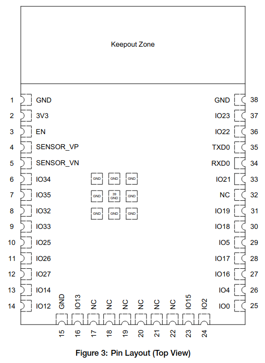
ESP32-WROOM32E
In this diagram you can see how the ESP32-WROOM module (PDF) pins are named using an IO# format. The ESP32 splits these 39 GPIO pins between two different GPIO ports. In Zephyr, the port for the first 32 GPIO pins is called &gpio0 (zero indexed), and the port for the last 7 GPIO pins are called &gpio1 (once again, zero indexed)
- GPIO0..GPIO31 → port
&gpio0, pins 0..31 - GPIO32..GPIO39 → port
&gpio1, pins 0..7
Following that scheme, it’s easy to translate the pins I need from the TTGO T-Display board (GPIO0 and GPIO35) into the numbers the devicetree understands. Because I’m using one of the pins numbered higher than GPIO31, I must switch to port 1 and adjust the pin number to begin counting again from zero – just subtract 32 from GPIO35 to get pin number 3.
&gpio0 0&gpio1 3
Pin Functions
The overlay file is also where you want to set up the expected behavior of the pin. Most importantly, this tells Zephyr if the pin will be active high or active low. This pin status addition is valid whether it’s an input or an output.
In the case of my TTGO T-Display board, there are pull-up resistors on the circuit board and pressing the button pulls the pin low, so these are “active low” buttons. Other boards might have pull-down resistors where pressing the button pulls the pin high. Zephyr lets you use the same application code for both boards, and the actual state is translated correctly by the overlay file.
There are other options available, including the ability to turn the ESP32’s internal pull-up/down resistors on. These flags can be added using logical OR:
gpios = <&gpio0 25 (GPIO_ACTIVE_LOW | GPIO_PULL_UP)>; |
Zephyr also makes interrupt-drive GPIO a snap. For more on this, study the basic/button sample which turns on the interrupts and adds a callback to the sw0 pin.
Initializing and Calling the Pins in Your Program
Before we finish up, let’s talk about accessing the pins you have set up in your overlay file. In main.c we need to get the alias and set up a struct that understands devicetree. From there, it’s the normal procedure of initializing the GPIO, and then acting on it: polling an input pin, or changing the state of an output.
First, we can define a node from the overlay file alias (esp32.overlay). That node is used to populate a struct that holds the port, pin number, and configuration of the GPIO pin.
#include <drivers/gpio.h>
#define SW0_NODE DT_ALIAS(sw0)
static const struct gpio_dt_spec button0 = GPIO_DT_SPEC_GET_OR(SW0_NODE, gpios, {0});
Second, we need to first initialize the pin in main.c. This function passes the port, pin number, and flags (ie: GPIO_ACTIVE_LOW). Note that we’ve added GPIO_INPUT here as an extra flag that sets the direction of the pin.
gpio_pin_configure_dt(&button0, GPIO_INPUT);
To act on the changes to the pin, we can poll its value do something if it is in the active state.
if (gpio_pin_get_dt(&button0) > 0)
{
    LOG_INF("Button0");
}
If we had set this pin as an output, the state changes happen in much the same way, but utilize a function to set the state: gpio_pin_set_dt(spec, value). Notice that the functions and macros that Zephyr uses here all include “dt” in them. This indicates that they are specialized to operate with the devicetree. There are functions to directly set up and manipulate GPIO without using an overlay file, but then you also lose out on the benefits of software portability. To fill in your knowledge around this, take a look at the GPIO section of the Zephyr docs.
ESP32 Overlays are a Snap
Pulling off an ESP32 demo is a snap now that you know how to address the pins. This is a great first adventure into how overlay files work, but of course they are far more powerful than buttons and LEDs. Sensors, displays, UARTs and just about everything else can be plumbed into Zephyr using the overlay file in order to take advantage of the libraries and drivers already present in the RTOS.
If you have questions or would like to discuss this in more detail, join the Zephyr community on Discord.