ARM V2M Beetle
Overview
The v2m_beetle board configuration is used by Zephyr applications that run on the V2M Beetle board. It provides support for the Beetle ARM Cortex-M3 CPU and the following devices:
- Nested Vectored Interrupt Controller (NVIC)
- System Tick System Clock (SYSTICK)
- Cortex-M System Design Kit GPIO
- Cortex-M System Design Kit UART
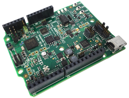
More information about the board can be found at the V2M Beetle Website.
Hardware
ARM V2M BEETLE provides the following hardware components:
- ARM Cortex-M3
- ARM IoT Subsystem for Cortex-M
- CORDIO Bluetooth Smart radio
- Memory
- 256KB of embedded flash
- 128KB SRAM
- 2MB of external QSPI flash.
- Debug
- JTAG, SWD & 4 bit TRACE
- CMSIS-DAP with a virtual UART port
- Arduino interface
- GPIO, UART, SPI, I2C
- Analog signals
Supported Features
The v2m_beetle board configuration supports the following hardware features:
| Interface | Controller | Driver/Component |
|---|---|---|
| NVIC | on-chip | nested vector interrupt controller |
| SYSTICK | on-chip | systick |
| UART | on-chip | serial port-polling; serial port-interrupt |
| PINMUX | on-chip | pinmux |
| GPIO | on-chip | gpio |
| WATCHDOG | on-chip | watchdog |
| TIMER | on-chip | timer |
Other hardware features are not currently supported by the port. See the V2M Beetle Website for a complete list of V2M Beetle board hardware features.
The default configuration can be found in the defconfig file:
boards/arm/v2m_beetle/v2m_beetle_defconfig
Interrupt Controller
Beetle is a Cortex-M3 based SoC and has 15 fixed exceptions and 45 IRQs.
A Cortex-M3/4-based board uses vectored exceptions. This means each exception calls a handler directly from the vector table.
Handlers are provided for exceptions 1-6, 11-12, and 14-15. The table here identifies the handlers used for each exception.
| Exc# | Name | Remarks | Used by Zephyr Kernel |
|---|---|---|---|
| 1 | Reset | system initialization | |
| 2 | NMI | system fatal error | |
| 3 | Hard fault | system fatal error | |
| 4 | MemManage | MPU fault | system fatal error |
| 5 | Bus | system fatal error | |
| 6 | Usage fault | undefined instruction, or switch attempt to ARM mode | system fatal error |
| 11 | SVC | context switch and software interrupts | |
| 12 | Debug monitor | system fatal error | |
| 14 | PendSV | context switch | |
| 15 | SYSTICK | system clock |
Pin Mapping
The ARM V2M Beetle Board has 4 GPIO controllers. These controllers are responsible for pin muxing, input/output, pull-up, etc.
All GPIO controller pins are exposed via the following sequence of pin numbers:
- Pins 0 - 15 are for GPIO 0
- Pins 16 - 31 are for GPIO 1
Mapping from the ARM V2M Beetle Board pins to GPIO controllers:
|
|
|
Peripheral Mapping:
|
|
|
For mode details please refer to Beetle Technical Reference Manual (TRM).
System Clock
V2M Beetle has one external and two on-chip oscillators. The slow clock is 32.768 kHz, and the main clock is 24 MHz. The processor can set up PLL to drive the master clock.
Serial Port
The ARM Beetle processor has two UARTs. Both the UARTs have only two wires for RX/TX and no flow control (CTS/RTS) or FIFO. The Zephyr console output, by default, is utilizing UART1.
Programming and Debugging
Flashing
CMSIS DAP
V2M Beetle provides:
- A USB connection to the host computer, which exposes a Mass Storage and an USB Serial Port.
- A Serial Flash device, which implements the USB flash disk file storage.
- A physical UART connection which is relayed over interface USB Serial port.
This interfaces are exposed via CMSIS DAP. For more details please refer to CMSIS-DAP Website.
Flashing an application to V2M Beetle
The sample application Hello World is being used in this tutorial:
$ZEPHYR_BASE/samples/hello_world
To build the Zephyr kernel and application, enter:
$ cd $ZEPHYR_BASE
$ . zephyr-env.sh
$ cd $ZEPHYR_BASE/samples/hello_world/
$ make BOARD=v2m_beetle
Connect the V2M Beetle to your host computer using the USB port and you should see a USB connection which exposes a Mass Storage (MBED) and a USB Serial Port. Copy the generated zephyr.bin in the MBED drive. Reset the board and you should be able to see on the corresponding Serial Port the following message:
Hello World! arm