NXP FRDM-KW41Z
Overview
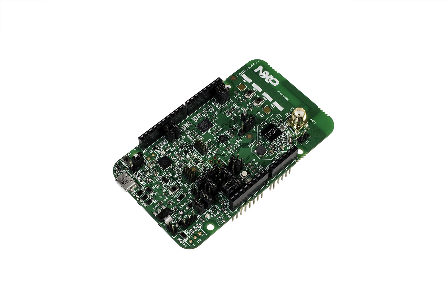
The FRDM-KW41Z is a development kit enabled by the Kinetis® W series KW41Z/31Z/21Z (KW41Z) family built on ARM® Cortex®-M0+ processor with integrated 2.4 GHz transceiver supporting Bluetooth® Smart/Bluetooth®Low Energy (BLE) v4.2, Generic FSK, IEEE® 802.15.4 and Thread.
The FRDM-KW41Z kit contains two Freedom boards that can be used as a development board or a shield to connect to a host processor. The FRDM-KW41Z is form-factor compatible with the Arduino™ R3 pin layout for more expansion options.
The FRDM-KW41Z highly-sensitive, optimized 2.4 GHz radio features a PCB F-antenna which can be bypassed to test via SMA connection, multiple power supply options, push/capacitive touch buttons, switches, LEDs and integrated sensors.
Hardware
- Can be configured as Host or Shield for connection to Host Processor
- Supports all DC-DC configurations (Buck, Boost, Bypass)
- PCB inverted F-type antenna
- SMA RF Connector
- RF regulatory certified
- Serial Flash for OTA firmware upgrades
- On board NXP FXOS8700CQ digital sensor, 3D Accelerometer (±2g/±4g/±8g) + 3D Magnetometer
- OpenSDA and JTAG debug
For more information about the KW41Z SoC and FRDM-KW41Z board:
- KW41Z Website
- KW41Z Datasheet
- KW41Z Reference Manual
- FRDM-KW41Z Website
- FRDM-KW41Z User Guide
- FRDM-KW41Z Schematics
Supported Features
The frdm_kw41z board configuration supports the following hardware features:
| Interface | Controller | Driver/Component |
|---|---|---|
| NVIC | on-chip | nested vector interrupt controller |
| SYSTICK | on-chip | systick |
| PINMUX | on-chip | pinmux |
| GPIO | on-chip | gpio |
| I2C | on-chip | i2c |
| UART | on-chip | serial port-polling; serial port-interrupt |
| FLASH | on-chip | soc flash |
| SENSOR | off-chip | fxos8700 polling: fxos8700 trigger |
The default configuration can be found in the defconfig file:
boards/arm/frdm_kw41z/frdm_kw41z_defconfig
Other hardware features are not currently supported by the port.
Connections and IOs
The KW41Z SoC has three pairs of pinmux/gpio controllers, but only two are currently enabled (PORTA/GPIOA and PORTC/GPIOC) for the FRDM-KW41Z board.
| Name | Function | Usage |
|---|---|---|
| PTC1 | GPIO | Red LED / FXOS8700 INT1 |
| PTA19 | GPIO | Green LED |
| PTA18 | GPIO | Blue LED |
| PTC2 | I2C1_SCL | I2C / FXOS8700 |
| PTC3 | I2C1_SDA | I2C / FXOS8700 |
| PTC4 | GPIO | SW3 |
| PTC5 | GPIO | SW4 |
| PTC6 | LPUART0_RX | UART Console |
| PTC7 | LPUART0_TX | UART Console |
System Clock
The KW41Z SoC is configured to use the 32 MHz external oscillator on the board with the on-chip FLL to generate a 40 MHz system clock.
Serial Port
The KW41Z SoC has one UART, which is used for the console.
Programming and Debugging
Flashing
The FRDM-KW41Z includes an OpenSDA serial and debug adaptor built into the board. The adaptor provides:
- A USB connection to the host computer, which exposes a Mass Storage and an USB Serial Port.
- A Serial Flash device, which implements the USB flash disk file storage.
- A physical UART connection which is relayed over interface USB Serial port.
Flashing an application to FRDM-KW41Z
The sample application Hello World is used for this example. Build the Zephyr kernel and application:
$ cd $ZEPHYR_BASE
$ . zephyr-env.sh
$ cd $ZEPHYR_BASE/samples/hello_world/
$ make BOARD=frdm_kw41z
Connect the FRDM-KW41Z to your host computer using the USB port and you should see a USB connection which exposes a Mass Storage (DAPLINK) and a USB Serial Port. Copy the generated zephyr.bin in the DAPLINK drive.
Reset the board and you should be able to see on the corresponding Serial Port the following message:
Hello World! arm