nRF52-PCA10040
Overview
Zephyr applications use the nrf52_pca10040 board configuration to run on the nRF52 Development Kit (PCA10040) hardware. It provides support for the Nordic Semiconductor nRF52832 ARM Cortex-M4F CPU and the following devices:
- NVIC
- RTC
- UART
- GPIO
- FLASH
- RADIO (Bluetooth Low Energy)
- Segger RTT (RTT Console)
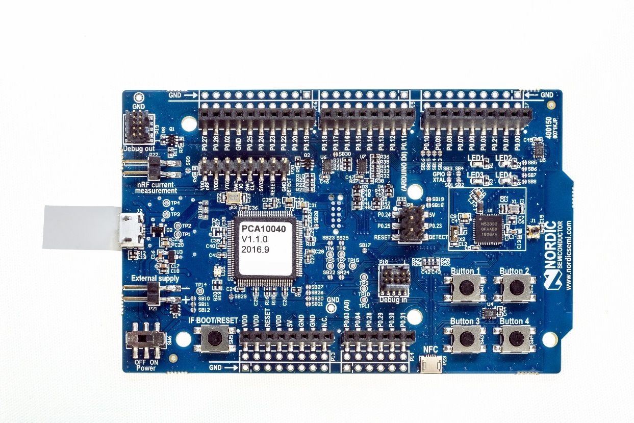
nRF52 PCA10040 DK (Credit: Nordic Semi)
More information about the board can be found at the nRF52 DK website [1]. The Nordic Semiconductor Infocenter [2] contains the processor’s information and the datasheet.
Hardware
nRF52 DK has two external oscillators. The frequency of the slow clock is 32.768 kHz. The frequency of the main clock is 32 MHz.
Supported Features
The nrf52_pca10040 board configuration supports the following hardware features:
| Interface | Controller | Driver/Component |
|---|---|---|
| NVIC | on-chip | nested vectored interrupt controller |
| RTC | on-chip | system clock |
| UART | on-chip | serial port |
| GPIO | on-chip | gpio |
| FLASH | on-chip | flash |
| RADIO | on-chip | bluetooth |
| RTT | on-chip | console |
Other hardware features are not supported by the Zephyr kernel. See nRF52 DK website [1] and Nordic Semiconductor Infocenter [2] for a complete list of nRF52 Development Kit board hardware features.
Connections and IOs
LED
- LED1 (green) = P0.17
- LED2 (green) = P0.18
- LED3 (green) = P0.19
- LED4 (green) = P0.20
- LD5 (red/green) = OB LED 1/2
Push buttons
- BUTTON1 = SW1 = P0.13
- BUTTON2 = SW2 = P0.14
- BUTTON3 = SW3 = P0.15
- BUTTON4 = SW4 = P0.16
- BOOT = SW5 = boot/reset
External Connectors
J-Link Prog Connector
| PIN # | Signal Name |
|---|---|
| 1 | VDD |
| 2 | IMCU_TMSS |
| 3 | GND |
| 4 | IMCU_TCKS |
| 5 | V5V |
| 6 | IMCU_TDOS |
| 7 | Cut off |
| 8 | IMCU_TDIS |
| 9 | Cut off |
| 10 | IMCU_RESET |
Debug IN
| PIN # | Signal Name | NRF52832 Functions |
|---|---|---|
| 1 | VDD | N/A |
| 2 | SWDIO | SWDIO |
| 3 | GND | N/A |
| 4 | SWDCLK | SWDCLK |
| 5 | GND | N/A |
| 6 | P0.18 | P0.18 / TRACEDATA[0] / SWO |
| 7 | Cut off | N/A |
| 8 | Cut off | N/A |
| 9 | GND | N/A |
| 10 | P0.21 | P0.21 / RESET |
Debug OUT
| PIN # | Signal Name |
|---|---|
| 1 | EXT_VTG |
| 2 | EXT_SWDIO |
| 3 | GND |
| 4 | EXT_SWDCLK |
| 5 | GND |
| 6 | EXT_SWO |
| 7 | Cut off |
| 8 | Cut off |
| 9 | EXT_GND_DETECT |
| 10 | EXT_RESET |
Shield Debug and Current measurement
| PIN # | Signal Name |
|---|---|
| 1 | VDD_nRF |
| 2 | VDD |
| 3 | SH_VTG |
| 4 | SH_SWDIO |
| 5 | SH_SWDCLK |
| 6 | SH_SWO |
| 7 | SH_RESET |
| 8 | SH_GND_DETECT |
Auxiliary
| PIN # | Signal Name | NRF52832 Functions |
|---|---|---|
| 1 | P0.00 | P0.00 / XL1 |
| 2 | P0.01 | P0.01 / XL2 |
| 3 | P0.21 | P0.21 / RESET |
| 4 | P0.05_C | P0.05 / AIN3 |
| 5 | P0.06_C | P0.06 |
| 6 | P0.07_C | P0.07 |
| 7 | P0.08_C | P0.08 |
| 8 | P0.09 | P0.09 / NFC1 |
| 9 | P0.10 | P0.10 / NFC2 |
Arduino Headers
P1/P7 Power
| PIN # | Signal Name | NRF52832 Functions |
|---|---|---|
| 1 | VDD | N/A |
| 2 | VDD | N/A |
| 3 | RESET | P0.21 / RESET |
| 4 | VDD | N/A |
| 5 | V5V | N/A |
| 6 | GND | N/A |
| 7 | GND | N/A |
| 8 | VIN | N/A |
P2/P8 Analog in
| PIN # | Signal Name | NRF52832 Functions |
|---|---|---|
| 1 | A0 | P0.03 / AIN1 |
| 2 | A1 | P0.04 / AIN2 |
| 3 | A2 | P0.28 / AIN4 |
| 4 | A3 | P0.29 / AIN5 |
| 5 | A4 | P0.30 / AIN6 |
| 6 | A5 | P0.31 / AIN7 |
P3/P9 Digital I/O
| PIN # | Signal Name | NRF52832 Functions |
|---|---|---|
| 1 | D0 (RX) | P0.11 |
| 2 | D1 (TX) | P0.12 |
| 3 | D2 | P0.13 |
| 4 | D3 | P0.14 / TRACEDATA[3] |
| 5 | D4 | P0.15 / TRACEDATA[2] |
| 6 | D5 | P0.16 / TRACEDATA[1] |
| 7 | D6 | P0.17 |
| 8 | D7 | P0.18 / TRACEDATA[3] / SWO |
P4/P10 Digital I/O
| PIN # | Signal Name | NRF52832 Functions |
|---|---|---|
| 1 | D8 | P0.19 |
| 2 | D9 | P0.20 / TRACECLK |
| 3 | D10 (SS) | P0.22 |
| 4 | D11 (MOSI) | P0.23 |
| 5 | D12 (MISO) | P0.24 |
| 6 | D13 (SCK) | P0.25 |
| 7 | GND | N/A |
| 8 | AREF | P0.02 / AIN0 |
| 9 | SDA | P0.26 |
| 10 | SCL | P0.27 |
P5/P11
| PIN # | Signal Name | NRF52832 Functions |
|---|---|---|
| 1 | D12 (MISO) | P0.24 |
| 2 | V5V | N/A |
| 3 | D13 (SCK) | P0.25 |
| 4 | D11 (MOSI) | P0.23 |
| 5 | RESET | N/A |
| 6 | N/A | N/A |
Programming and Debugging
Flashing
Follow the instructions in the Nordic nRF5x Segger J-Link page to install and configure all the necessary software.
This tutorial uses the sample application
shell $ZEPHYR_BASE/samples/shell, and uses the information that can be found in
Flashing.
To build the Zephyr kernel, enter:
$ cd $ZEPHYR_BASE
$ make -C samples/shell BOARD=nrf52_pca10040
Connect the micro-USB cable to the nRF52 DK and to your computer.
Erase the flash memory in the nRF52832:
$ nrfjprog --eraseall -f nrf52Flash the application using the nrfjprog tool:
$ nrfjprog --program outdir/zephyr.hex -f nrf52Run your favorite terminal program to listen for output.
$ minicom -D <tty_device> -b 115200
Replace
<tty_device>with the port where the board nRF52 DK can be found. For example, under Linux,/dev/ttyACM0.The
-boption sets baudrate ignoring the value from config.Press the Reset button and you should see the output of shell application in your terminal.
Debugging
Refer to the Nordic nRF5x Segger J-Link page to learn about debugging Nordic boards with a Segger IC.
Testing the LEDs and buttons in the nRF52 DK
There are 2 samples that allow you to test that the buttons (switches) and LEDs on the board are working properly with Zephyr:
samples/basic/blinky
samples/basic/button
You can build and flash the examples to make sure Zephyr is running correctly on
your board. The button and LED definitions can be found in boards/arm/nrf52_pca10040/board.h.
References
| [1] | (1, 2) http://www.nordicsemi.com/eng/Products/Bluetooth-low-energy/nRF52-DK |
| [2] | (1, 2) http://infocenter.nordicsemi.com/ |