Hexiwear
Overview
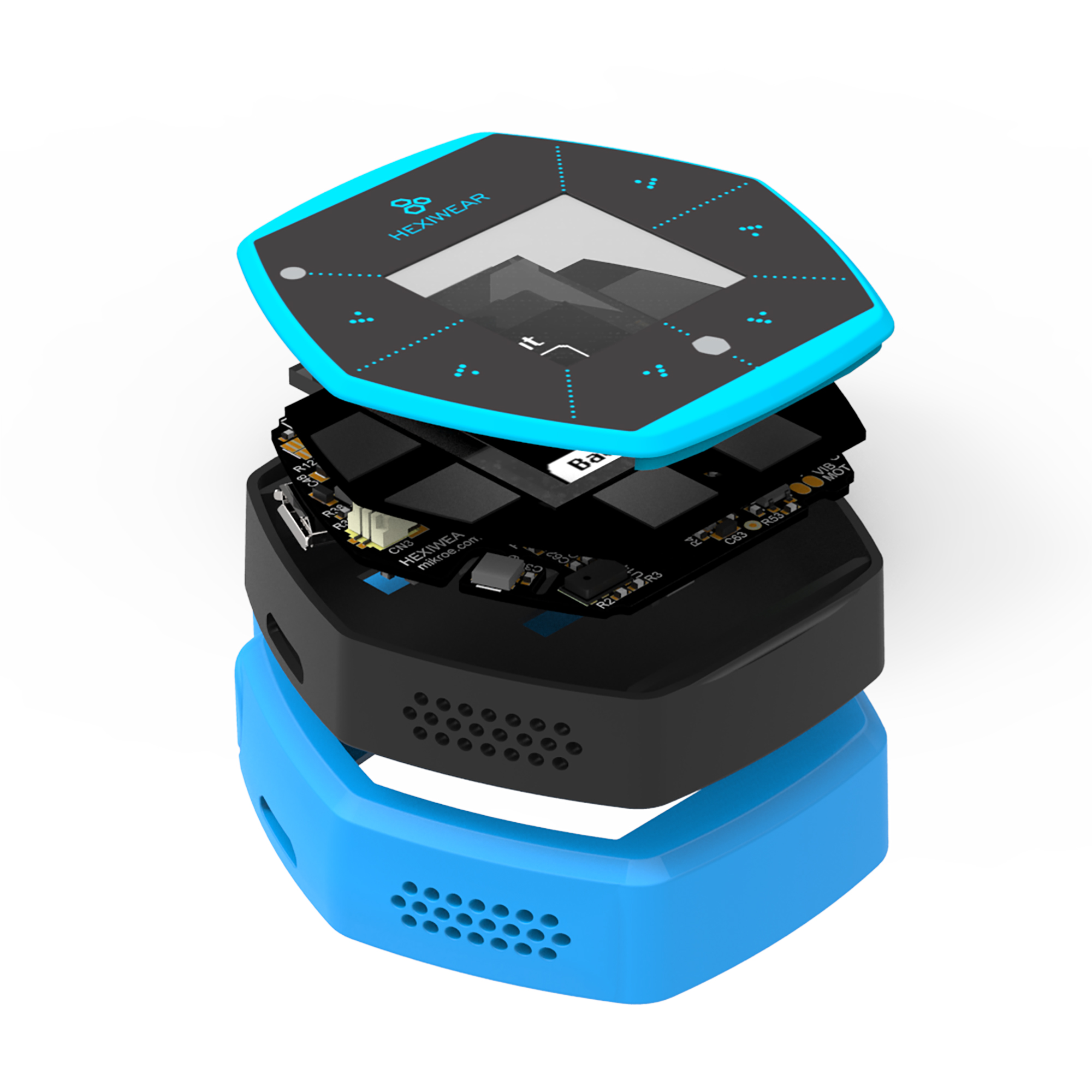
Hexiwear is powered by a Kinetis K64 microcontroller based on the ARM Cortex-M4 core. Another Kinetis wireless MCU, the KW40Z, provides Bluetooth Low Energy connectivity. Hexiwear also integrates a wide variety of sensors, as well as a user interface consisting of a 1.1” 96px x 96px full color OLED display and six capacitive buttons with haptic feedback.
- Eye-catching Smart Watch form factor with powerful, low power Kinetis K6x MCU and 6 on-board sensors.
- Designed for wearable applications with the onboard rechargeable battery, OLED screen and onboard sensors such as optical heart rate, accelerometer, magnetometer and gyroscope.
- Designed for IoT end node applications with the onboard sensor’s such as temperature, pressure, humidity and ambient light.
- Flexibility to let you add the sensors of your choice nearly 200 additional sensors through click boards.
Hardware
- Main MCU: NXP Kinetis K64x (ARM Cortex-M4, 120 MHz, 1M Flash, 256K SRAM)
- Wireless MCU: NXP Kinetis KW4x (ARM Cortex-M0+, Bluetooth Low Energy & 802.15.4 radio)
- 6-axis combo Accelerometer and Magnetometer NXP FXOS8700
- 3-Axis Gyroscope: NXP FXAS21002
- Absolute Pressure sensor NXP MPL3115
- Li-Ion/Li-Po Battery Charger NXP MC34671
- Optical heart rate sensor Maxim MAX30101
- Ambient Light sensor, Humidity and Temperature sensor
- 1.1” full color OLED display
- Haptic feedback engine
- 190 mAh 2C Li-Po battery
- Capacitive touch interface
- RGB LED
For more information about the K64F SoC and Hexiwear board:
- K64F Website
- K64F Datasheet
- K64F Reference Manual
- Hexiwear Website
- Hexiwear Fact Sheet
- Hexiwear Schematics
Supported Features
The hexiwear_k64 board configuration supports the following hardware features:
| Interface | Controller | Driver/Component |
|---|---|---|
| NVIC | on-chip | nested vector interrupt controller |
| SYSTICK | on-chip | systick |
| PINMUX | on-chip | pinmux |
| GPIO | on-chip | gpio |
| I2C | on-chip | i2c |
| UART | on-chip | serial port-polling; serial port-interrupt |
| FLASH | on-chip | soc flash |
| SENSOR | off-chip | fxos8700 polling; fxos8700 trigger |
The default configuration can be found in the defconfig file:
boards/arm/hexiwear_k64/hexiwear_k64_defconfig
Other hardware features are not currently supported by the port.
Connections and IOs
The K64F SoC has five pairs of pinmux/gpio controllers.
| Name | Function | Usage |
|---|---|---|
| PTC8 | GPIO | Red LED |
| PTC9 | GPIO | Green LED |
| PTD0 | GPIO | Blue LED |
| PTD13 | GPIO | FXOS8700 INT2 |
| PTB16 | UART0_RX | UART Console |
| PTB17 | UART0_TX | UART Console |
| PTE24 | UART4_RX | UART BT HCI |
| PTE25 | UART4_TX | UART BT HCI |
| PTC10 | I2C1_SCL | I2C / FXOS8700 |
| PTC11 | I2C1_SDA | I2C / FXOS8700 |
System Clock
The K64F SoC is configured to use the 12 MHz external oscillator on the board with the on-chip PLL to generate a 120 MHz system clock.
Serial Port
The K64F SoC has six UARTs. One is configured for the console, another for BT HCI, and the remaining are not used.
Programming and Debugging
Flashing
The Hexiwear docking station includes an OpenSDA serial and debug adaptor built into the board. The adaptor provides:
- A USB connection to the host computer, which exposes a Mass Storage and an USB Serial Port.
- A Serial Flash device, which implements the USB flash disk file storage.
- A physical UART connection which is relayed over interface USB Serial port.
Note
The OpenSDA is shared between the K64 and the KW40Z via switches, therefore only one SoC can be flashed, debugged, or have an open console at a time.
Flashing an application to Hexiwear
Build the Zephyr kernel and application:
$ cd $ZEPHYR_BASE
$ . zephyr-env.sh
$ cd $ZEPHYR_BASE/samples/hello_world/
$ make BOARD=hexiwear_k64
Make sure the docking station USB cable is unplugged.
Attach the Hexiwear board to the docking station.
Configure the docking station switches to route the desired SoC signals to the OpenSDA circuit:
Switch Signal KW40Z K64 1 MK64 SWDIO OFF ON 2 MK64 RST OFF ON 3 MKW40 RST ON OFF 4 MKW40 SWDIO ON OFF 5 OSDA ON ON 6 LED1 OFF OFF 7 LED2 OFF OFF 8 LED3 OFF OFF Attach the USB cable and make sure the power switch is ON. A USB Mass Storage Device called DAPLINK will enumerate.
Copy the application binary
zephyr.binto the DAPLINK drive. The drive will temporarily disappear, then reappear after several seconds.Open a serial terminal (minicom, putty, etc.) with the following settings:
- Speed: 115200
- Data: 8 bits
- Parity: None
- Stop bits: 1
Reset the SoC. Each SoC has a reset button on docking station. You should see the following message on the Serial Port:
Hello World! arm
Using Bluetooth
Configure the KW40Z as a Bluetooth controller
The K64 can support Zephyr Bluetooth host applications when you configure the KW40Z as a Bluetooth controller.
- Download and install the KW40Z Connectivity Software. This package contains Bluetooth controller application for the KW40Z.
- Flash the file
tools/binaries/BLE_HCI_Modem.binto the KW40Z.
Now you can build and run the sample Zephyr Bluetooth host applications on the K64. You do not need to repeat this step each time you flash a new Bluetooth host application to the K64.
Peripheral Heart Rate Sensor
Navigate to the Zephyr sample application and build it for the Hexiwear K64.
$ cd samples/bluetooth/peripheral_hr
$ make BOARD=hexiwear_k64
Flash the application to the Hexiwear K64. Make sure the OpenSDA switches on the docking station are configured for the K64.
Reset the KW40Z and the K64 using the push buttons on the docking station.
Install the Kinetis BLE Toolbox on your smartphone:
Open the app, tap the Heart Rate feature, and you should see a Zephyr Heartrate Sensor device. Tap the Zephyr Heartrate Sensor device and you will then see a plot of the heart rate data that updates once per second.