NXP FRDM-KL25Z
Overview
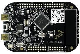
The Freedom KL25Z is an ultra-low-cost development platform for Kinetis® L Series KL1x (KL14/15) and KL2x (KL24/25) MCUs built on ARM® Cortex®-M0+ processor.
The FRDM-KL25Z features include easy access to MCU I/O, battery-ready, low-power operation, a standard-based form factor with expansion board options and a built-in debug interface for flash programming and run-control.
Hardware
- MKL25Z128VLK4 MCU @ 48 MHz, 128 KB flash, 16 KB SRAM, USB OTG (FS), 80LQFP
- On board capacitive touch “slider”, MMA8451Q accelerometer, and tri-color LED
- OpenSDA debug interface
For more information about the KL25Z SoC and FRDM-KL25Z board:
- KL25Z Website
- KL25Z Datasheet
- KL25Z Reference Manual
- FRDM-KL25Z Website
- FRDM-KL25Z User Guide
- FRDM-KL25Z Schematics
Supported Features
The frdm_kl25z board configuration supports the following hardware features:
| Interface | Controller | Driver/Component |
|---|---|---|
| NVIC | on-chip | nested vector interrupt controller |
| SYSTICK | on-chip | systick |
| PINMUX | on-chip | pinmux |
| GPIO | on-chip | gpio |
| UART | on-chip | serial port-polling; serial port-interrupt |
| I2C | on-chip | i2c |
| SPI | on-chip | spi |
| FLASH | on-chip | soc flash |
The default configuration can be found in the defconfig file:
boards/arm/frdm_kl25z/frdm_kl25z_defconfig
Other hardware features are not currently supported by the port.
Connections and IOs
The KL25Z SoC has five pairs of pinmux/gpio controllers, and all are currently enabled (PORTA/GPIOA, PORTB/GPIOB, PORTC/GPIOC, PORTD/GPIOD, and PORTE/GPIOE) for the FRDM-KL25Z board.
| Name | Function | Usage |
|---|---|---|
| PTB18 | GPIO | Red LED |
| PTB19 | GPIO | Green LED |
| PTD1 | GPIO | Blue LED |
| PTA1 | UART0_RX | UART Console |
| PTA2 | UART0_TX | UART Console |
| PTE24 | I2C0_SCL | I2C |
| PTE25 | I2C0_SDA | I2C |
| PTC4 | SPI0_PSC0 | SPI |
| PTC5 | SPI0_SCK | SPI |
| PTC6 | SPI0_MOSI | SPI |
| PTC7 | SPI0_MISO | SPI |
System Clock
The KL25Z SoC is configured to use the 8 MHz external oscillator on the board with the on-chip FLL to generate a 48 MHz system clock.
Serial Port
The KL25Z UART0 is used for the console.
Programming and Debugging
The FRDM-KL25Z includes the NXP OpenSDA serial and debug adapter built into the board to provide debugging, flash programming, and serial communication over USB.
To use the pyOCD tools with OpenSDA, follow the instructions in the pyOCD page using the DAPLink FRDM-KL25Z Firmware.
To use the Segger J-Link tools with OpenSDA, follow the instructions in the Segger J-Link page using the Segger J-Link OpenSDA V2.1 Firmware.
Flashing
This example uses the Hello World sample with the
pyOCD tools. Use the make flash build target to build
your Zephyr application, invoke the pyOCD flash tool and program your Zephyr
application to flash.
$ cd <zephyr_root_path>
$ . zephyr-env.sh
$ cd samples/hello_world/
$ make BOARD=frdm_kl25z FLASH_SCRIPT=pyocd.sh flash
Open a serial terminal (minicom, putty, etc.) with the following settings:
- Speed: 115200
- Data: 8 bits
- Parity: None
- Stop bits: 1
Reset the board and you should be able to see on the corresponding Serial Port the following message:
Hello World! arm
Debugging
This example uses the Hello World sample with the
pyOCD tools. Use the make debug build target to build
your Zephyr application, invoke the pyOCD GDB server, attach a GDB client, and
program your Zephyr application to flash. It will leave you at a gdb prompt.
$ cd <zephyr_root_path>
$ . zephyr-env.sh
$ cd samples/hello_world/
$ make BOARD=frdm_kl25z DEBUG_SCRIPT=pyocd.sh debug