Arduino/Genuino 101
Overview
The Arduino/Genuino 101 is a learning and development board which contains an Intel® Curie™ Module. This board is designed to integrate the core’s low power-consumption and high performance with the Arduino’s ease-of-use. The Arduino 101 adds Bluetooth Low Energy capabilities and has an on-board 6-axis accelerometer/gyroscope, providing exciting opportunities for building creative projects in the connected world.
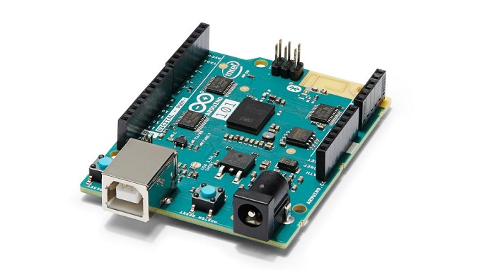
Arduino/Genuino 101 (Credit: Intel)
The Intel Quark* SE SoC in the Curie module contains a single core 32 MHz x86 (Intel Quark* processor) and the 32 MHz Argonaut RISC Core (ARC)* EM processor. The two processors operate simultaneously and share memory. The ARC processor is also referenced as the digital signal processor (DSP) sensor hub or a sensor subsystem depending on what document you’re looking at. In theory, the DSP can run using a minimal amount of power, gathering and processing sensor data while the x86 processor waits in a low power mode, which would be ideal for always-on applications.
Zephyr can be flashed to an Arduino 101 for experimentation and testing purposes; keep in mind that running the Zephyr OS on the Arduino 101 is not supported by Arduino LLC.
Hardware
Board Layout
General information for the board can be found at the Arduino 101 website, which also includes schematics and BRD files for the board.
Arduino 101 Pinout
When using the Zephyr kernel, the pinout mapping for the Arduino 101 becomes a
little more complicated. The table below details which pins in Zephyr map to
those on the Arduino 101 board for control. Full details of the pinmux
implementation, what valid options can be configured, and where things map can
be found in the boards/arduino_101/pinmux.c file.
| Arduino Pin | Function | Zephyr Pin |
|---|---|---|
| IO-0 | UART1-RX | 17 |
| IO-1 | UART1-TX | 16 |
| IO-2 | GPIO | 52 |
| IO-3 | GPIO | 51 63 |
| IO-4 | GPIO | 53 |
| IO-5 | GPIO | 49 64 |
| IO-6 | PWM2 | 65 |
| IO-7 | GPIO | 54 |
| IO-8 | GPIO | 50 |
| IO-9 | PWM3 | 66 |
| IO-10 | AIN0 | 0 |
| IO-11 | AIN3 | 3 |
| IO-12 | AIN1 | 1 |
| IO-13 | AIN2 | 2 |
| ADC0 | GPIO SS | 10 |
| ADC1 | GPIO SS | 11 |
| ADC2 | GPIO SS | 12 |
| ADC3 | GPIO SS | 13 |
| ADC4 | AIN14 | 14 |
| ADC5 | AIN9 | 9 |
Supported Features
The Zephyr kernel supports multiple hardware features on the Arduino 101 through the use of drivers. Some drivers are functional on the x86 side only, some on the ARC side only, and a few are functional on both sides. The table below shows which drivers and functionality can be found on which architectures:
| Interface | Controller | ARC | x86 | Driver/Component |
|---|---|---|---|---|
| APIC | on-chip | N | Y | interrupt_controller |
| UART | on-chip | N | Y | serial port-polling; serial port-interrupt |
| SPI | on-chip | Y | Y | spi |
| ADC | on-chip | Y | N | adc |
| I2C | on-chip | Y | Y | i2c |
| GPIO | on-chip | Y | Y | gpio |
| PWM | on-chip | Y | Y | pwm |
| mailbox | on-chip | Y | Y | ipm |
Required Hardware and Software
Before flashing the Zephyr kernel onto an Arduino 101, a few additional pieces of hardware are required.
- The USB port for power will work; however, we recommend the 7V-12V barrel connector be used when working with the JTAG connector.
- If you wish to grab any data off the serial port, you will need a TTY-to-USB
adaptor. The following adapters require male-to-male jumper cables in order to
connect to the Arduino 101 board.
- USB to TTL Serial Cable
- FTDI USB to TTL Serial Part #TTL-232R-3V3 http://www.ftdichip.com/Products/Cables/USBTTLSerial.htm
We recommend using the dfu-util to flash the Arduino 101 board. If you’d
like to flash using JTAG, the following additional hardware is needed:
- FlySwatter2 JTAG debugger
- ARM Micro JTAG Connector, Model: ARM-JTAG-20-10
Connecting Serial Output
The default configuration defined in the Zephyr kernel supports serial output via the UART0 on the board. To read the output, you will need a USB to TTL serial cable. To enable serial output:
- Connect the Serial Cable RX pin to the Arduino 101’s TX->1 pin.
- Connect the Serial Cable TX pin to the Arduino 101’s RX<-0 pin.
- Connect the Serial Cable GND pin to the Arduino 101’s GND pin.
Once connected, on your development environment, you will need to:
- Open a serial port emulator (i.e. on Linux minicom, screen, etc)
- Attach to the USB to TTL Serial cable, for example, on Linux this may be /dev/ttyUSB0
- Set the communication details to:
- Speed: 115200
- Data: 8 bits
- Parity: None
- Stopbits: 1
Programming and Debugging
The Arduino 101 is powered by a Quark CPU and a sensor subsystem powered by an ARC processor. When building applications, depending on the usage, two Zephyr images need to be built and flashed.
The Arduino 101 has a bootloader that supports flashing over USB using the DFU protocol. Additionally, the factory installed bootloader supports flashing of the firmware for the Bluetooth device of the Curie module.
Use the arduino_101 board definition to build a kernel for the Quark core. Use
the arduino_101_sss board definition when targeting the sensor subsystem.
When your application is targeting the Quark processor only, it is important to disable the sensor subsystem processor using the CONFIG_ARC_INIT option. otherwise the board will appear to hang waiting for the sensor subsystem processor to boot.
Bootloader (Boot ROM)
Support for the QMSI Bootloader has been removed starting from Zephyr 1.4.0. Thus, the factory boot ROM can be kept supporting the flashing of the board over DFU and flashing the Bluetooth firmware.
If you have previously installed a different boot ROM it is recommended to restore the factory boot ROM image using the Flashpack Utility. Consult the README available in the Flashpack Utility package and follow the instructions for your environment.
Flashing
The dfu-util flashing application will only recognize the Arduino 101 as a
DFU-capable device within five seconds after the Master Reset is pressed on the
board. Type the dfu-util command line, press the Master Reset button, and then
quickly press return to execute the dfu-util command. If dfu-util fails saying
“No DFU capable USB device available”, try again more quickly after pressing
the master reset button.
Flashing the Sensor Subsystem Core
When building for the ARC processor, the board type is listed as
arduino_101_sss.
The sample application Hello World is used for this tutorial. Change directories to your local checkout copy of Zephyr, and run:
$ cd $ZEPHYR_BASE/samples/hello_world
$ make BOARD=arduino_101_sss
Once the image has been built, flash it with:
$ dfu-util -a sensor_core -D outdir/arduino_101_sss/zephyr.bin
Flashing the x86 Application Core
When building for the x86 processor, the board type is listed as
arduino_101.
Change directories to your local checkout copy of Zephyr, and run:
$ cd $ZEPHYR_BASE/samples/hello_world
$ make BOARD=arduino_101
Verify the Arduino 101 has power.
Once the image has been built, flash it with:
$ dfu-util -a x86_app -D outdir/arduino_101/zephyr.bin
Flashing the Bluetooth Core
To be interoperable with the Zephyr Bluetooth stack the Bluetooth controller of the Arduino 101 (Nordic Semiconductor nRF51) needs to be flashed with a compatible firmware.
The Arduino 101 factory-installed firmware on this controller is not supported by the Zephyr project, so you need to flash a new one onto it.
Luckily, starting with Zephyr 1.6, Zephyr itself is able to act as the firmware
for the controller. The application you need is samples/bluetooth/hci_uart and
the target board is called arduino_101_ble.
To build the Bluetooth controller image, follow the instructions below:
$ cd samples/bluetooth/hci_uart
$ make BOARD=arduino_101_ble
Flash the binary using USB DFU:
$ dfu-util -a ble_core -D outdir/arduino_101_ble/zephyr.bin
After successfully completing these steps your Arduino 101 should now have a HCI compatible BLE firmware.
Flashing using JTAG Adapter
We recommend using the dfu-util tool to flash the Arduino 101 board for typical
development work. JTAG is intended for for advanced development and debugging.
Connect the ARM Micro JTAG Connector to the FlySwatter2.
Locate the micro JTAG connector on the Arduino 101 board. It is adjacent to the SCL and SDA pins in the Arduino headers, highlighted as the red square in the figure below.
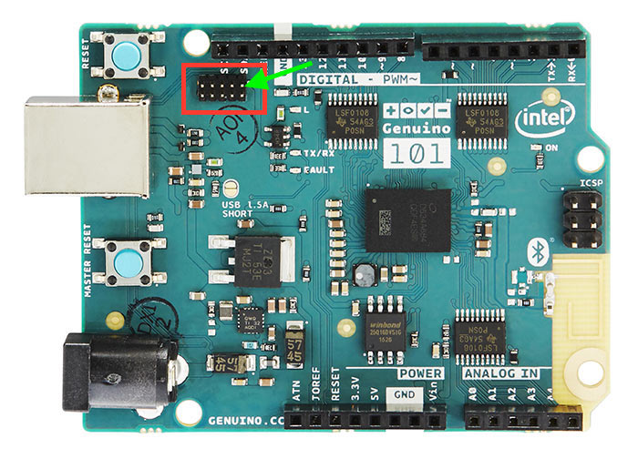
Beside the micro JTAG header is a small white dot indicating the location of pin 1 on the header. The orange arrow on the figure points to the dot.
Connect the FlySwatter2 to the Arduino 101 micro JTAG connector.
Ensure that both the cable and header pin 1 locations line up. The cable from the ARM Micro JTAG connector uses a red wire on the cable to denote which end on the cable has the pin 1.
For Linux environments, to control the FlySwatter your Linux account needs to be granted HAL layer interaction permissions. This is done through the group ‘plugdev’. Verifying the group exists and adding your username can be accomplished with the usermod command:
$ sudo usermod -a -G plugdev $USERNAME
If the group does not exist, you can add it by running the following command:
$ sudo groupadd -r plugdev
For Linux environments, verify that udev has the proper rules for giving your
user control of the FlySwatter device. Adding the following rule to udev will
give members of the plugdev group control of the FlySwatter.
$ su -
$ cat <<EOF > /etc/udev/rules.d/99-openocd.rules
# TinCanTools FlySwatter2
ATTRS{idVendor}=="0403", ATTRS{idProduct}=="6010", MODE="664", GROUP="plugdev"
EOF
Once your udev rules are setup, you will need to reload the rules:
$ sudo udevadm control --reload-rules
Plug the USB Type B cable into the FlySwatter2 and your computer. On Linux, you should see something similar to the following in your dmesg:
usb 1-2.1.1: new high-speed USB device number 13 using xhci_hcd
usb 1-2.1.1: New USB device found, idVendor=0403, idProduct=6010
usb 1-2.1.1: New USB device strings: Mfr=1, Product=2, SerialNumber=3
usb 1-2.1.1: Product: Flyswatter2
usb 1-2.1.1: Manufacturer: TinCanTools
usb 1-2.1.1: SerialNumber: FS20000
ftdi_sio 1-2.1.1:1.0: FTDI USB Serial Device converter detected
usb 1-2.1.1: Detected FT2232H
usb 1-2.1.1: FTDI USB Serial Device converter now attached to ttyUSB0
ftdi_sio 1-2.1.1:1.1: FTDI USB Serial Device converter detected
usb 1-2.1.1: Detected FT2232H
usb 1-2.1.1: FTDI USB Serial Device converter now attached to ttyUSB1
Debugging
The instructions below will help you debug the Arduino 101 on the x86 core or the ARC core, respectively.
Application Core (X86)
Build and flash the x86 application with the following commands:
$ cd <my x86 app>
$ make BOARD=arduino_101 flash
Launch the debug server on the x86 core:
$ make BOARD=arduino_101 debugserver
Connect to the debug server at the x86 core from a second console:
$ cd <my x86 app>
$ /opt/zephyr-sdk/sysroots/i686-pokysdk-linux/usr/bin/iamcu-poky-elfiamcu/i586-poky-elfiamcu-gdb outdir/arduino_101/zephyr.elf
(gdb) target remote localhost:3333
(gdb) b main
(gdb) c
Sensor Subsystem Core (ARC)
Enable ARC INIT from the x86 core. This can be done by flashing an x86 app (like a simple hello world or dummy app) with CONFIG_ARC_INIT=y.
$ cd samples/hello_world
$ make BOARD=arduino_101 flash
Build and flash the ARC app as shown:
$ cd <my arc app>
$ make BOARD=arduino_101_sss flash
Launch the debug server on the ARC core:
$ make BOARD=arduino_101_sss debugserver
Connect to the debugserver at ARC from a second console:
$ cd <my arc app>
$ /opt/zephyr-sdk/sysroots/i686-pokysdk-linux/usr/bin/arc-poky-elf/arc-poky-elf-gdb outdir/arduino_101_sss/zephyr.elf
(gdb) target remote localhost:3334
(gdb) b main
(gdb) c
Bluetooth Firmware
You will only see normal log messages on the console, by default, without any way of accessing the HCI traffic between Zephyr and the nRF51 controller. However, there is a special Bluetooth logging mode that converts the console to use a binary protocol that interleaves both normal log messages as well as the HCI traffic. Set the following Kconfig options to enable this protocol before building your application:
CONFIG_BLUETOOTH_DEBUG_MONITOR=y
CONFIG_UART_CONSOLE=n
CONFIG_UART_QMSI_1_BAUDRATE=1000000
The first item replaces the BLUETOOTH_DEBUG_STDOUT option, the second one disables the default printk/printf hooks, and the third one matches the console baudrate with what’s used to communicate with the nRF51, in order not to create a bottle neck.
To decode the binary protocol that will now be sent to the console UART you need to use the btmon tool from BlueZ 5.40 or later:
$ btmon --tty <console TTY> --tty-speed 1000000
Release Notes
When debugging on ARC, it is important that the x86 core be started and running BEFORE attempting to debug on ARC. This is because the IPM console calls will hang waiting for the x86 core to clear the communication.