Arduino 101
Overview
The Arduino 101 board is an Arduino product with an Intel® Curie™ module. Zephyr can be flashed to an Arduino 101 for experimentation and testing purposes; keep in mind this is configuration is unsupported by Arduino.
The Intel Curie module contains both an ARC and an X86 core, so be sure to
flash an ARC and an X86 image if you wish to use both. Either
arduino_101_factory (for x86) or arduino_101_sss_factory (for ARC)
board configurations work to build a Zephyr Kernel that can be flashed to and
run on the Arduino 101 platform. The default configuration for Arduino 101
boards can be found in
boards/arduino_101/arduino_101_factory_defconfig for the X86 and
boards/arduino_101_sss/arduino_101_sss_factory_defconfig for the ARC.
This release removes the support for the alternate boot ROM. Thus, the original boot ROM can be kept supporting the flashing of the board over DFU and flashing the Bluetooth firmware.
See the documentation for releases up to v1.3.0 for details on how to use an alternate boot ROM.
If you have previously installed a different boot ROM it is recommended to restore the original boot ROM image as described in the Backup and Restore Factory Settings section.
Board Layout
General information for the board can be found at the Arduino website, which also includes schematics and BRD files.
Supported Features
The Zephyr kernel supports multiple hardware features on the Arduino 101 through the use of drivers. Some drivers are functional on the x86 side only, some on the ARC side only, and a few are functional on both sides. The table below shows which drivers and functionality can be found on which architectures:
| Interface | Controller | ARC | x86 | Driver/Component |
|---|---|---|---|---|
| APIC | on-chip | N | Y | interrupt_controller |
| UART | on-chip | N | Y | serial port-polling; serial port-interrupt |
| SPI | on-chip | Y | Y | spi |
| ADC | on-chip | Y | N | adc |
| I2C | on-chip | Y | Y | i2c |
| GPIO | on-chip | Y | Y | gpio |
| PWM | on-chip | Y | Y | pwm |
| mailbox | on-chip | Y | Y | ipm |
Required Hardware and Software
Before flashing the Zephyr kernel onto an Arduino 101, a few additional pieces of hardware are required.
- The USB port for power will work; however, we recommend the 7V-12V barrel connector be used when working with the JTAG connector.
- The Zephyr SDK
- If you wish to grab any data off the serial port, you will need a TTY-to-USB
adaptor. The following adapters require male-to-male jumper cables in order
to connect to the Arduino 101 board.
- USB to TTL Serial Cable
- FTDI USB to TTL Serial Part #TTL-232R-3V3 http://www.ftdichip.com/Products/Cables/USBTTLSerial.htm
To flash using the JTAG the following hardware is needed:
- FlySwatter2 JTAG debugger
- ARM Micro JTAG Connector, Model: ARM-JTAG-20-10
Connecting Serial Output
In the default configuration, Zephyr’s Arduino 101 images support serial output via the UART0 on the board. To read the output, you will need a USB to TTL serial cable. To enable serial output:
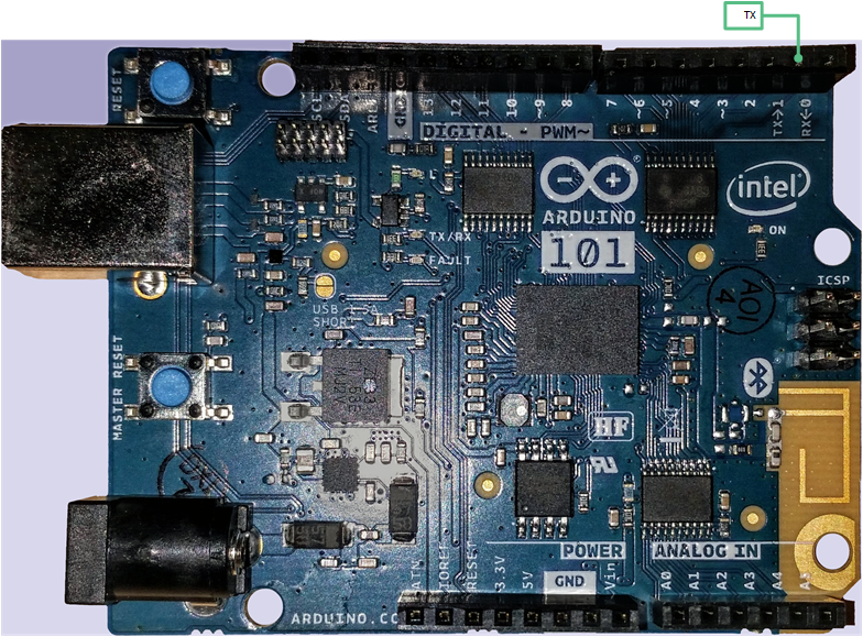
Connect the Serial Cable RX pin to the Arduino 101’s TX->1 pin.
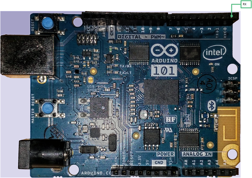
Connect the Serial Cable TX pin to the Arduino 101’s RX<-0 pin.
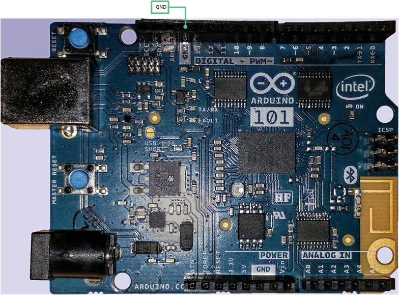
Connect the Serial Cable GND pin to the Arduino 101’s GND pin.
Once connected, on your development environment, you will need to:
- Open a serial port emulator (i.e. on Linux minicom, screen, etc)
- Attach to the USB to TTL Serial cable, for example, on Linux this may be
/dev/ttyUSB0 - Set the communication details to:
- Speed: 115200
- Data: 8 bits
- Parity: None
- Stopbits: 1
Building an Application
The Arduino 101 is powered by a Quark CPU and a sensor sub-system powered by an ARC processor. When building applications, depending on the usage, two Zephyr image need to be built and flashed.
The Arduino 101 has a bootloader that supports flashing over USB using the DFU protocol. Flashing over USB keeps the original bootloader intact and does not require a JTAG adapter. Additionally, the factory installed bootloader supports flashing of the firmware for the Bluetooth device of the Curie module.
Use the arduino_101_factory board definition to build a kernel for the Quark
core. Use the arduino_101_sss_facotry board definition when targeting the
sensor sub-system.
To use an alternate boot ROM different board definitions are needed for both the
Quark and the sensor sub-system cores: For the Quark, use arduino_101
and for the sensor-subsystem, use arduino_101_sss.
When your application is targeting the Quark processor only, it is important to disable the sensor sub-system processor. otherwise the board will appear to hang waiting for the sensor sub-system processor to boot.
See the Debugging on Arduino 101 section for details on how to disable the sensor sub-system.
Flashing using USB DFU
Flashing the Sensor Subsystem Core
Make sure the binary image has been built. Change directories to your local checkout copy of Zephyr, and run:
$ source ./zephyr-env.sh
$ cd $ZEPHYR_BASE/samples/hello_world/nanokernel
$ make pristine && make BOARD=arduino_101_sss_factory
Verify the Arduino 101 has power.
Once the image has been built, flash it with:
$ dfu-util -a sensor_core -D outdir/zephyr.bin
Note
When building for the ARC processor, the board type is listed as arduino_101_sss_factory.
Congratulations, you have now flashed the hello_world image to the ARC processor.
Flashing the x86 Application Core
Make sure the binary image has been built. Change directories to your local checkout copy of Zephyr, and run:
$ source ./zephyr-env.sh
$ cd $ZEPHYR_BASE/samples/hello_world/nanokernel
$ make pristine
$ make BOARD=arduino_101_factory
Verify the Arduino 101 has power.
Once the image has been built, flash it with:
$ dfu-util -a x86_app -D outdir/zephyr.bin
Note
When building for the x86 processor, the board type is listed as arduino_101_factory.
Congratulations you have now flashed the hello_world image to the x86 processor.
Flashing the Bluetooth Core
To be interoperable with the Zephyr Bluetooth stack the Bluetooth controller of the Arduino 101 (Nordic Semiconductor nRF51) needs to be flashed with a compatible firmware. The instructions for acquiring and flashing the firmware are found here
Flashing using JTAG Adapter
Use this method only for advanced development and debugging.
Connect the ARM Micro JTAG Connector to the FlySwatter2.
Locate the micro JTAG connector on the Arduino 101 board. It is adjacent to the SCL and SDA pins in the Arduino headers, highlighted as the red square in the figure below.
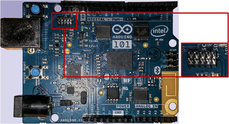
Beside the micro JTAG header is a small white dot indicating the location of pin 1 on the header. The orange arrow on the figure points to the dot.

Connect the FlySwatter2 to the Arduino 101 micro JTAG connector.
Ensure that both the cable and header pin 1 locations line up. The cable from the ARM Micro JTAG connector uses a red wire on the cable to denote which end on the cable has the pin 1.
For Linux environments, to control the FlySwatter your user needs to be granted HAL layer interaction permissions. This is done through the group ‘plugdev’. Verifying the group exists and adding your username can be accomplished with the useradd function:
$ sudo useradd -G plugdev $USERNAME
For Linux environments, verify that udev has the proper rules for giving your user control of the FlySwatter device. Adding the following rule to udev will give members of the plugdev group control of the FlySwatter.
$ su -
# cat <<EOF > /etc/udev/rules.d/99-openocd.rules
# TinCanTools FlySwatter2
ATTRS{idVendor}=="0403", ATTRS{idProduct}=="6010", MODE="664", GROUP="plugdev"
EOF
Once your udev rules are setup, you will need to reload the rules:
$ sudo udevadm control --reload-rulesPlug the USB Type B cable into the FlySwatter2 and your computer. On Linux, you should see something similar to the following in your dmesg:
usb 1-2.1.1: new high-speed USB device number 13 using xhci_hcd
usb 1-2.1.1: New USB device found, idVendor=0403, idProduct=6010
usb 1-2.1.1: New USB device strings: Mfr=1, Product=2, SerialNumber=3
usb 1-2.1.1: Product: Flyswatter2
usb 1-2.1.1: Manufacturer: TinCanTools
usb 1-2.1.1: SerialNumber: FS20000
ftdi_sio 1-2.1.1:1.0: FTDI USB Serial Device converter detected
usb 1-2.1.1: Detected FT2232H
usb 1-2.1.1: FTDI USB Serial Device converter now attached to ttyUSB0
ftdi_sio 1-2.1.1:1.1: FTDI USB Serial Device converter detected
usb 1-2.1.1: Detected FT2232H
usb 1-2.1.1: FTDI USB Serial Device converter now attached to ttyUSB1
Backup and Restore Factory Settings
Before continuing, consider creating a backup image of the ROM device as it stands today. This would be necessary if you wanted to run Arduino sketches on the hardware again, as the Arduino IDE requires updating via a USB flashing method that is not currently supported by Zephyr.
Typically Arduino hardware can re-program the Bootloader by connecting the ICSP header and issuing the “Burn Bootloader” option from the Arduino IDE. On the Arduino 101, this option is not provided.
Confirm the Zephyr SDK has been installed on your platform.
Open a terminal window.
Verify the JTAG debugger is properly attached to the Arduino 101 board and to the host computer.
Connect the Arduino 101 to a power source.
Open a terminal window
Change directories to
$ZEPHYR_BASE.Source the
zephyr-env.shfile.In the terminal window, enter:
$ ./boards/arduino_101/support/arduino_101_backup.shNote
This command tells the JTAG to dump two files in your
$ZEPHYR_BASE: directory:A101_BOOT.binandA101_OS.bin. These contain copies of the original flash, which can be used to restore the state of the board to factory conditions.
Done! You have finished creating a backup for the Arduino 101.
To restore the factory settings of the Arduino 101 device, use the provided script.
In the terminal window, enter:
$ ./boards/arduino_101/support/arduino_101_load.shNote
This script expects two files in your
$ZEPHYR_BASEdirectory namedA101_OS.binandA101_BOOT.bin.
Flashing the Sensor Subsystem Core
Make sure the binary image has been built. Change directories to your local checkout copy of Zephyr, and run:
$ source ./zephyr-env.sh
$ cd $ZEPHYR_BASE/samples/hello_world/nanokernel
$ make pristine
$ make BOARD=arduino_101_sss_factory
Verify the JTAG debugger is properly attached to the Arduino 101 board.
Verify the Arduino 101 has power.
Once the image has been built, flash it with:
$ make BOARD=arduino_101_sss_factory flash
Note
When building for the ARC processor, the board type is listed as arduino_101_sss.
Congratulations, you have now flashed the hello_world image to the ARC processor.
Flashing the x86 Application Core
Make sure the binary image has been built. Change directories to your local checkout copy of Zephyr, and run:
$ source ./zephyr-env.sh
$ cd $ZEPHYR_BASE/samples/hello_world/nanokernel
$ make pristine
$ make BOARD=arduino_101_factory
Verify the JTAG debugger is properly attached to the Arduino 101 board.
Verify the Arduino 101 has power.
Once the image has been built, flash it with:
$ make BOARD=arduino_101_factory flash
Note
When building for the x86 processor, the board type is listed as arduino_101_factory.
Congratulations you have now flashed the hello_world image to the x86 processor.
Debugging on Arduino 101
The image file used for debugging must be built to the corresponding core that you wish to debug. For example, the binary must be built for BOARD=arduino_101_factory if you wish to debug on the quark core.
Build the binary for your application on the architecture you wish to debug. Alternatively, use the instructions above as template for testing.
When debugging on ARC, you will need to enable the
CONFIG_ARC_GDB_ENABLEconfiguration option in your local kernel configuration file. Details of this flag can be found inarch/x86/soc/quark_se/Kconfig. Setting this variable will force the ARC processor to halt on bootstrap, giving the debugger a chance at connecting and controlling the hardware.This can be done by editing the file
samples/hello_world/nanokernel/prj.confto include:CONFIG_ARC_INIT=y CONFIG_ARC_GDB_ENABLE=y
Note
By enabling
CONFIG_ARC_INIT, you MUST flash both an ARC and an X86 image to the hardware. If you do not, the X86 image will appear to hang at boot while it is waiting for the ARC to finish initialization.Open two terminal windows.
In terminal window 1, type:
$ cd $ZEPHYR_BASE/samples/hello_world/nanokernel
$ make BOARD=arduino_101_factory debugserver
These commands will start an
openocdsession with a local telnet server (on port 4444 for direct openocd commands to be issued), and a gdbserver (for gdb access). The command should not return to a command line interface until you are done debugging, at which point you can pressCtrl+Cto shutdown everything.Start GDB in terminal window 2:
To debug on x86:
$ cd $ZEPHYR_BASE/samples/hello_world/nanokernel
$ gdb outdir/zephyr.elf
gdb$  target remote :3333
To debug on ARC:
ARC debugging will require some extra steps and a third terminal. It is necessary to use a version of gdb that understands ARC binaries. Thankfully one is provided with the Zephyr SDK at
$ZEPHYR_SDK_INSTALL_DIR/sysroots/i686-pokysdk-linux/usr/bin/arc-poky-elf/arc-poky-elf-gdb.It is suggested to create an alias in your shell to run this command, such as:
alias arc_gdb= "$ZEPHYR_SDK_INSTALL_DIR/sysroots/i686-pokysdk-
linux/usr/bin/arc-poky-elf/arc-poky-elf-gdb"
On Terminal 2:
$ cd $ZEPHYR_BASE/samples/hello_world/nanokernel
$ arc_gdb outdir/zephyr.elf
gdb$  target remote :3334
At this point you may set the breakpoint needed in the code/function.
On Terminal 3 connect to the X86 side:
$ gdb
gdb$  target remote :3333
gdb$  continue
Note
In previous versions of the SDK, the gdbserver remote ports were reversed. The gdb ARC server port was 3333 and the X86 port was 3334. As of SDK v0.7.2, the gdb ARC server port is 3334, and the X86 port is 3333.
The
continueon the X86 side is needed as the ARC_GDB_ENABLE flag has been set and halts the X86 until the ARC core is ready. Ready in this case is defined as openocd has had a chance to connect, setup registers, and any breakpoints. Unfortunately, there exists no automated method for notifying the X86 side that openocd has connected to the ARC at this time.Once you’ve started the X86 side again, and have configured any debug stubs on the ARC side, you will need to have gdb issue the continue command for the ARC processor to start.
Arduino 101 Pinout
When using the Zephyr kernel, the pinout mapping for the Arduino 101 becomes a
little more complicated. The table below details which pins in Zephyr map to
those on the Arduino 101 board for control. Full details of the pinmux
implementation, what valid options can be configured, and where things map can
be found in the boards/arduino_101/pinmux.c.
| Arduino Pin | Function | Zephyr Pin |
|---|---|---|
| IO-0 | UART1-RX | 17 |
| IO-1 | UART1-TX | 16 |
| IO-2 | GPIO | 52 |
| IO-3 | GPIO | 51 63 |
| IO-4 | GPIO | 53 |
| IO-5 | GPIO | 49 64 |
| IO-6 | PWM2 | 65 |
| IO-7 | GPIO | 54 |
| IO-8 | GPIO | 50 |
| IO-9 | PWM3 | 66 |
| IO-10 | AIN0 | 0 |
| IO-11 | AIN3 | 3 |
| IO-12 | AIN1 | 1 |
| IO-13 | AIN2 | 2 |
| ADC0 | GPIO SS | 10 |
| ADC1 | GPIO SS | 11 |
| ADC2 | GPIO SS | 12 |
| ADC3 | GPIO SS | 13 |
| ADC4 | AIN14 | 14 |
| ADC5 | AIN9 | 9 |
Note
IO-3 and IO-5 require both pins to be set for functionality changes.
Release Notes
When debugging on ARC, it is important that the x86 core be started and running BEFORE attempting to debug on ARC. This is because the IPM console calls will hang waiting for the x86 core to clear the communication.